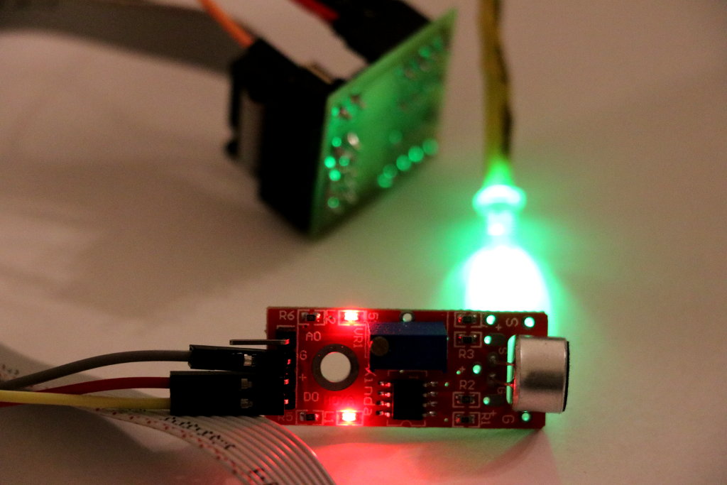
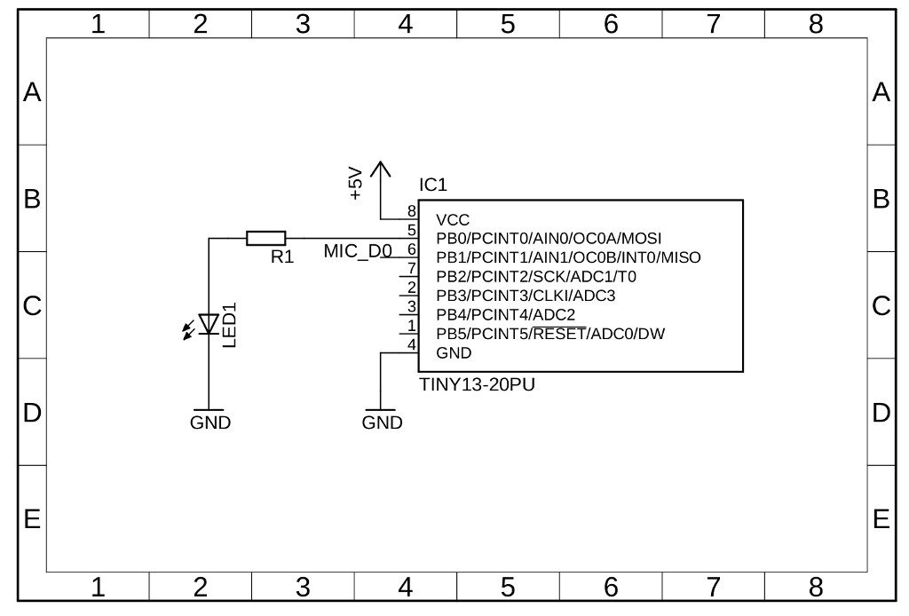
This project shows how turn ATtiny13 with sound detector module into smart Clap Clap Switch. The project has been designed to react on only double claps (clap clap – ON, clap clap – OFF). So, how it works? There is one pin for a MIC (digital output from sound detector module) and one pin for a LED (to show on/off cases). External interrupt (INT0) has been used to check microphone state. In the main loop there is an algorithm which take care of processes of detecting claps, counters, resetting states and toggling the LED. The user of this smart clap-clap switch has a wide timeframe <100ms; 1s> between first and second clap. In my opinion, It’s enough of time for a double clap but feel free to experiment with other values! The single clap / noises should not affect the process of double-clap detecting (what was the goal!). This project can be easly extended by adding extra components like for example relay to control high voltage devices. The code is on Github, click here.
Parts Required
- ATtiny13 – i.e. MBAVR-1 development board
- sound detector module – i.e. based on LM393
- Resistor – 220Ω, see LED Resistor Calculator
- LED
Circuit Diagram
Software
This code is written in C and can be compiled using the avr-gcc. All information about how to compile this project is here.
/**
 * Copyright (c) 2019, Łukasz Marcin Podkalicki <lpodkalicki@gmail.com>
 * ATtiny13/050
 * Clap-Clap Switch.
 */

#include <avr/io.h>
#include <avr/interrupt.h>
#include <util/delay.h>

#define LED_PIN PB0
#define MIC_PIN PB1

static volatile uint8_t state = 0;

int
main(void)
{
    uint8_t reset = 0, claps = 0;

    /* setup */
    DDRB |= _BV(LED_PIN); // set LED pin as output
    MCUCR &= ~(_BV(ISC01)|_BV(ISC00)); // trigger INT0 interrupt when low level detected
    GIMSK |= _BV(INT0); // enable INT0 interrupt
    sei(); // enable global interrupts

    /* loop */
    while (1) {
        /* if single clap detected then start procedure */
        if (state) {
            claps++; // increment claps count
            if (claps == 1) { // if it's first clap,
                reset = 0; // set reset counter to zero
            } else if (claps == 2) { // if it's second clap,
                PORTB ^= _BV(LED_PIN); // toggle LED on/off
                claps = reset = 0; // and set initial values
            }
            state = 0; // for each clap detection, reset state
           _delay_ms(200); // and wait 0.2s
        }
        /* if rest counter is max (1s) then set initial values */
        if (++reset >= 10) {
            claps = state = reset = 0;
        }
        _delay_ms(100); // loop delay
    }
}

ISR(INT0_vect)
{

    state = 1;
}


hello, does this code work on Attiny 85?
Hi, It should work but I didn’t test it on Attiny85.
/LP
Would you by any chance have any knowledge on how to make this project work on ATmega 32? Been trying to make it work for ages for a school project, and I’m kind of stuck. Thanks in advance.
Hi,
you can try port this code to any AVR chip (including ATtiny10). Should be easy to do so.
/L
Hi
Thanks for the many great examples!
Do you have a simple example of how to read PB1 or PB2 as a bushbutton input?
Thanks in advance!
T.
Hi;
Im new on AVR microcontroller and i wanna ask some question. Firstly your project is so good and instructional. there is something I can’t understand what “state” variable is purpose
why did you give that variable a value of 1 in the external “ISR” interrupt. I’d appreciate it if you could enlighten me on this.
Hi, the value of state is set to “1” to indicate that interrupt has occured. Note that in the algorithm inside the main loop the value of state is reset to “0” for every interrupt detection.
/L