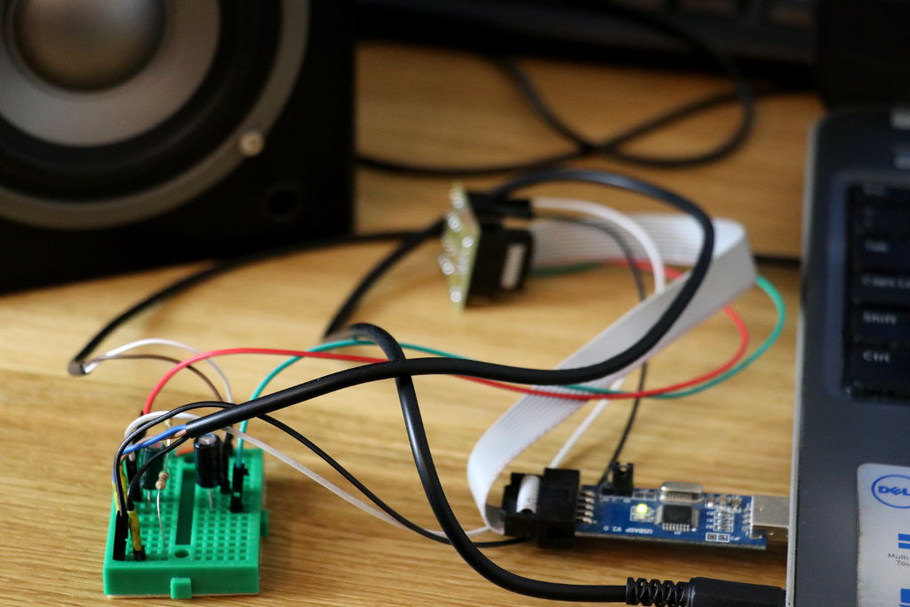
I always wonder whether it is possible to make an amplifier of class D on ATtiny13 or not. Some time ago I found George Gardner’s project based on ATtiny85 – TinyD. It was a sign to start challenging it with ATtiny13. It took me a few hours but finally I made it! The code is very short and useses a lot of hardware settings which has been explained line-by-line in the comments. The project runs on ATtiny13 with maximum internal clock source (9.6MHz). It gave me posibility to use maximum of hardware PWM frequency (Fast PWM mode).
The PWM freqency of class D amplifiers should be of course much higher, a hundreds of kHz (some sources says 8 times more than sampling frequency). Unfortunately, in case of ATtiny13 it’s not posible to achieve such parameters. However, for experimentally selected settings of ADC sampling rate (~10kHz) and PWM frequency (37.5kHz) the amplifier sounds very good! The code is on Github, click here.
Software
This code is written in C and can be compiled using the avr-gcc. All information about how to compile this project is here.
/**
 * Copyright (c) 2019, Łukasz Marcin Podkalicki <lpodkalicki@gmail.com>
 * ATtiny13/052
 * Example of 8bit mono class D amplifier.
 */

#include <avr/io.h>
#include <avr/interrupt.h>
#include <util/delay.h>

#define	AUDIO_IN	PB3
#define	AUDIO_OUT	PB0

int
main(void)
{

	/* setup */
	DDRB |= _BV(AUDIO_OUT); // set AUDIO_OUT pin as output
	TCCR0A |= _BV(WGM01)|_BV(WGM00); // set timer mode to FAST PWM
	TCCR0A |= _BV(COM0A1); // connect PWM pin to channel A
	TCCR0B |= _BV(CS00); // set prescaler to 1
	ADMUX |= _BV(MUX0)|_BV(MUX1); // select ADC3 (PB3)
	ADMUX |= _BV(REFS0); // set internal 1.1V reference voltage
	ADMUX |= _BV(ADLAR); // left adjust of ADC result
	ADCSRA |= _BV(ADPS1)|_BV(ADPS0); // set ADC division factor to 8
	ADCSRA |= _BV(ADEN)|_BV(ADIE); // enable ADC and interrupt
	ADCSRA |= _BV(ADATE); // set ADC auto-trigger
	ADCSRA |= _BV(ADSC); // start conversion
	sei(); // enable global interrupts

	/* loop */
	while (1);
}

ISR(ADC_vect)
{

	OCR0A = ADCH; // the magic
}
References

very interesting for a guitar pedal
been a while since visiting this project page…
new projects that sparked my interest…
the updated disco light using DFT and this Mono amp..
just a quick question…. what is the equivalent audio power output (RMS) of the ATtiny13 mono amp?
thanks again for the interesting projects..!
Hi, and welcome back! This little amplifier has only 5 Vpp (1.8 V RMS) and we should consider maximum 40mA load for AVR GPIO. I never measured it but I think it’s about ~80mW RMS.
/LP
Thanks for sharing – neat project. Could you also post the schematic, please?
Ah, it’s single-ended, with a 220µF capacitor in series with the speaker (which goes to VCC).
CMOS 4049B also makes a good Class D amp.
how make code in arduino uno sir please example
I’m flattered; thanks for giving credit. Now to go stereo!
George, thanks for TinyD! I learned a lot while studying your project. Some day will try stereo but for now I’m going to port the code to ATtiny10-tshr.
/L
I noticed a few things from your code, you are using PB2 for sampling data, not PB3 like in your schematic.
Also you set ADC prescaler to /8, with the clock rate of 9.6MHz it gives ADC clock 1.2MHz. Because conversion takes 13 clocks, sampling rate is actually ~92KHz.
Hi Darko! Thank you for code review! At the begining I choose ADC on PB2 for prototyping. However, it look better on schematic when I use ADC on PB3. I will change the code to reflect exactly what is on circuit.
You’re calculation regarding sampling frequency are correct. I thought it will work with calculated frequency (I assumed safe 25 cycles per sample) but simple test – toggling I/O inside a interrupt hook – showed about 5 kHz on oscilloscope. Probably Timer consumes a lot of time. Whould be great if someone else could make this test.
/L
Hi Łukasz! I’ve checked your project with oscilloscope and I have 4.52…kHz on PB0 without input signal. It seems, that all modulation will be with this frequency, not with 37.5kHz.
Wow, I didn’t expect that good quality from that tiny thing… Really nice project!
Good job!